Dumping old ECUs (P30 analysis p.1)
Different cars, different goals
Backstory
I’ve had a few cars since I came to Japan and while my daytime job is more about nowadays ECU reversing and pentesting, I’ve always enjoyed poking at the ones in my cars to understand how things worked back in the days and how tuning was done.
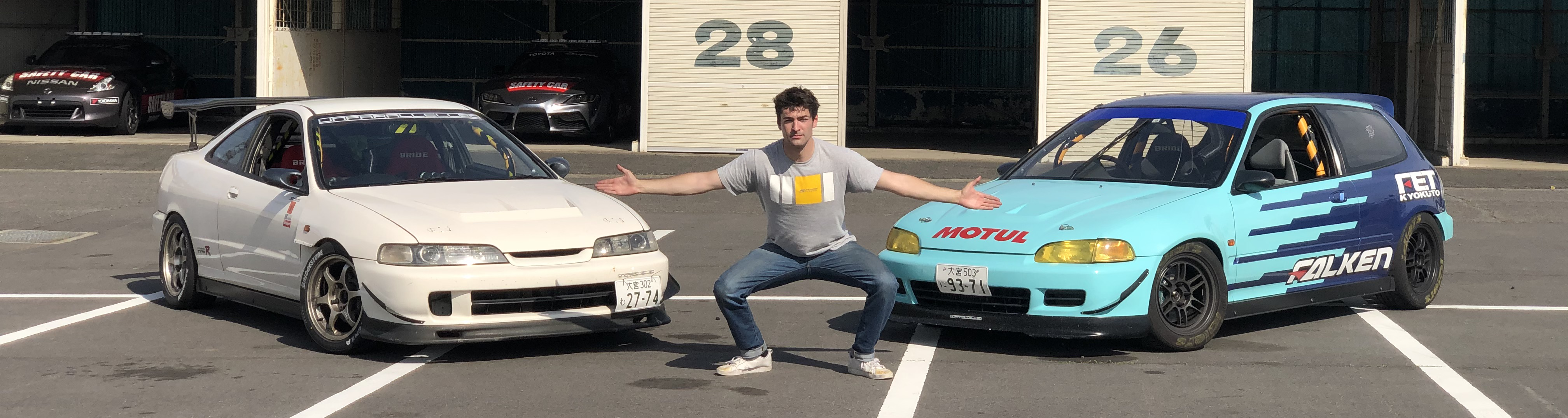
Both cars I own right now, a 1995 Honda Integra on the left and a 1993 Honda Civic on the right have tuned ECUs based on the stock ones, which means the
circuitry is roughly the same as it was 25~30 years ago, and the firmware is
just a modified version of the original one (by this I mean it’s not running a recent
aftermarket computer). Both cars have very similar engines (only differ in
displacement), so the original engine management is also pretty much the same
from factory. The ECUs though differ quite a bit more, hardware wise.
In my case, both have different tunes: the Integra’s ECU has a Spoon Sports
Race tune (VTEC at 4900RPM, higher rev limit [redline] and no speed limiter)
and the Civic’s tuning origins are unknown at the moment.
The Integra’s chassis code is DC2, and the Civic’s is EG6. I will use those from now on as there were a lot of different Civics and a lot of different Integras to which this analysis doesn’t relate.
When the EG6’s ECU randomly burnt a few transistors a month ago (see pictures below), it was taken to a tuning shop here in Japan to be repaired. I there chatted with the owner, who we’ll call Tuner-san, who used to work for Spoon back in the days.
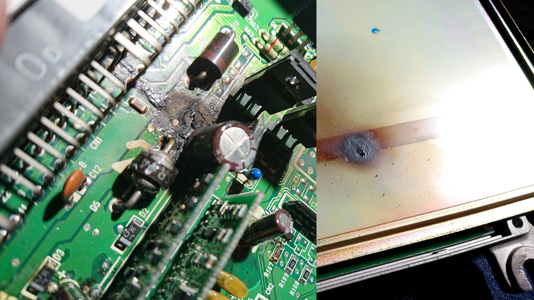
He repaired my ECU by replacing the components and removing the burnt material, and now it’s as good as new. But before returning it to me, he told me he copied the firmware of this unknown tuning, for backup purposes, and this is where things got interesting.
He told me that when he was young, people played console games (like Famicom), but games were expensive. So they would buy one cardridge, and somehow copy it for friends using EPROM programmers.
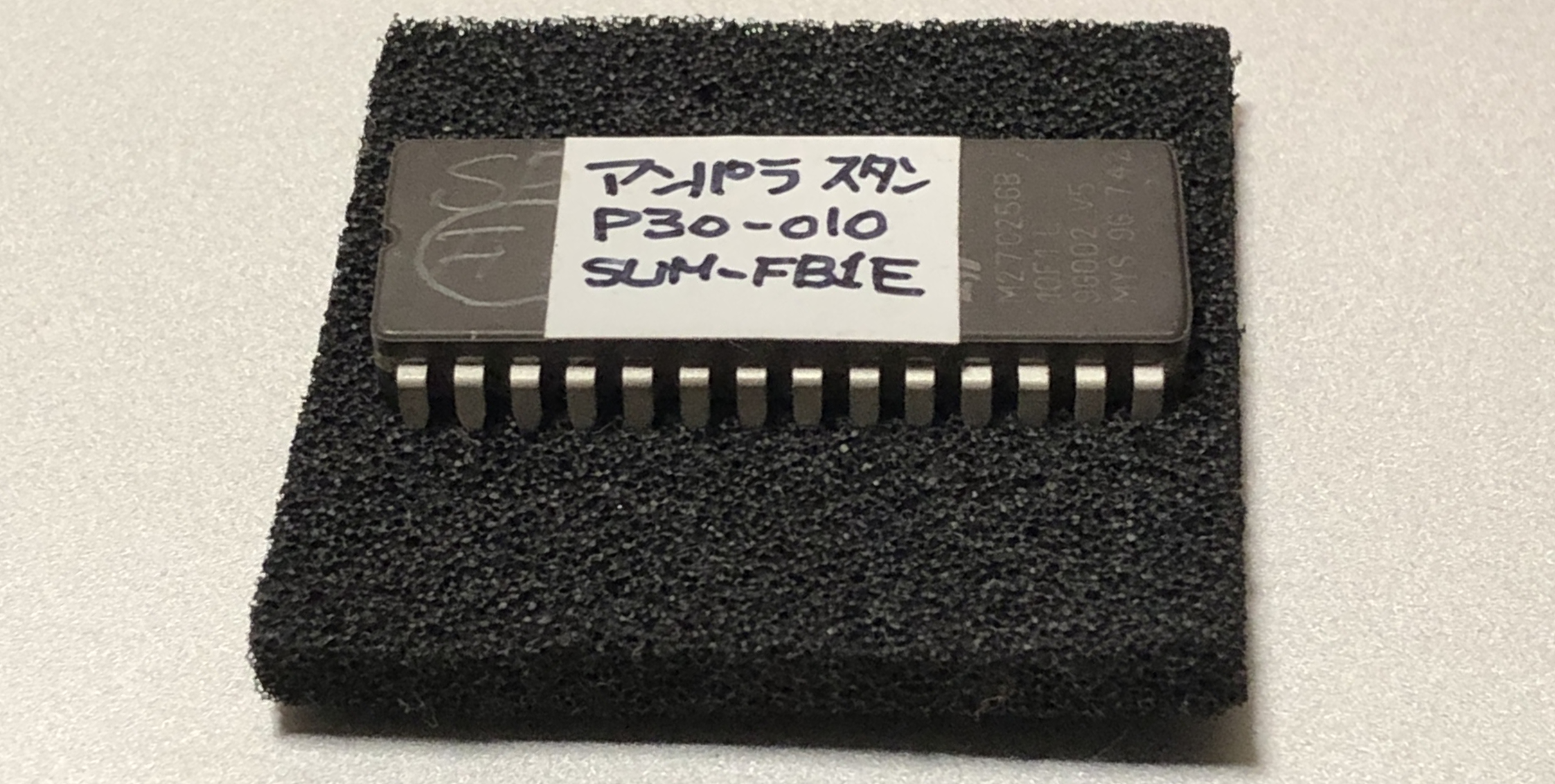
He pulled a small case and showed me a collection of labelled EPROMS, all containing different EG6 firmwares and tunes from the early 90s that he copied using the very same machine his friends used years ago to copy said games: the Advantest R4945A. He keeps them for backup purpose and to reflash ECUs when they have already been retuned; indeed, the stock ECUs came with a non-writable (OTP) ROM, and thus required the tuner to remove the ROM, dump it, modify what he had to, and copy it on another EPROM that would replace the stock one. Those EPROMs are now out of production and thus stupidly expensive, which is why people tend to turn to some full-aftermarket solutions instead now.
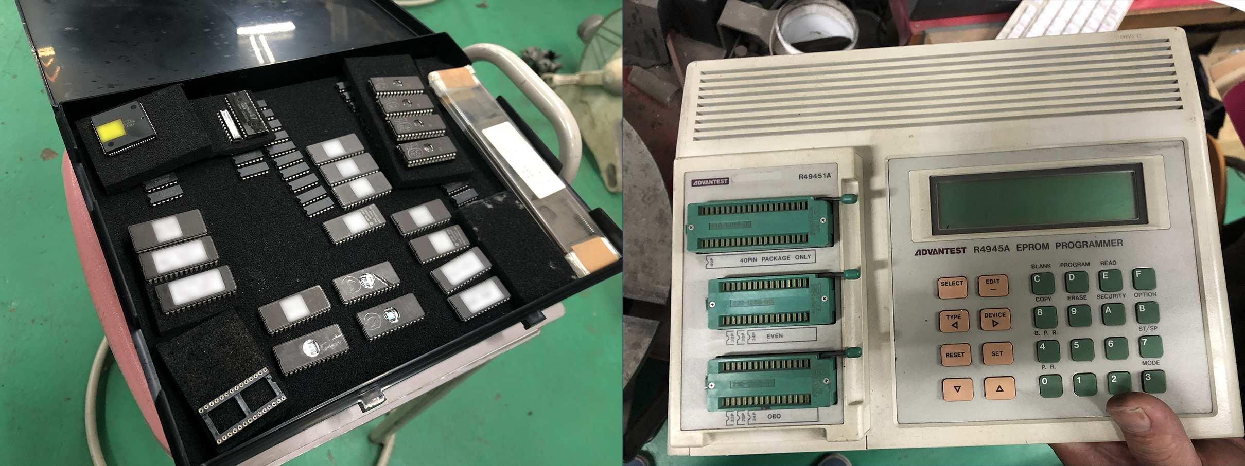
He proudly showed me the newest addition to his collection: my EG6’s unknown firmware. I asked a few details about it, like where is it from and what’s different compared to the Spoon one, but since he can only copy the firmware from one chip to another using his machine, he had no mean of actually reading the code and answer my questions. It was really only here for backup, or to be blindly copied on other chips. So I asked if we could dump it, and he said it would be amazing if we could, and we laughed.
But I was really curious and since I still lack decent hardware knowledge, I asked two good friends (hey Phil and JF) what they thought of this. They looked through the pictures I sent them and told me that they saw two ways to do that: the first one is using the serial port behind the R4945A machine and its remote control protocol to somehow dump the chips, or directly parallel dump the chips with a lot of wires. First method didn’t work because the pinout of the serial port didn’t match exactly the RS232-DB25 cable I had, and since I wanted to learn more about EPROMs I went for the second option.
Dumping the EPROMs
So what I’m gonna explain there is nothing amazing (it was for me who had never done that before) and actually quite trivial. But for the sake of putting all the information together for future reference or if anybody is trying to do the same thing, I’m going to describe how I did that.
First, the EPROMs themselves. I found a very good reference here that taught me everything I needed to know (or didn’t need, but still interesting):
- An empty EPROM is full of 0xFF (all bits are turned to 1 when the EPROM is erased)
- When programming a bit we can only change a 1 to a 0. We can do multiple passes to change more 1s to 0s, for example changing a A5h byte (10100101) to 21h (00100001), but it can’t be changed back to F5h (11110101).
- EPROMs are pretty sensitive to electric charge and exposure duration, so it’s important to refer to the datasheet to properly understand how to program and erase one.
For our case though, which is dumping (basically reading) the chip, we don’t need to worry about programming or erasing at all, which makes everything easier. How does one read an EPROM though?
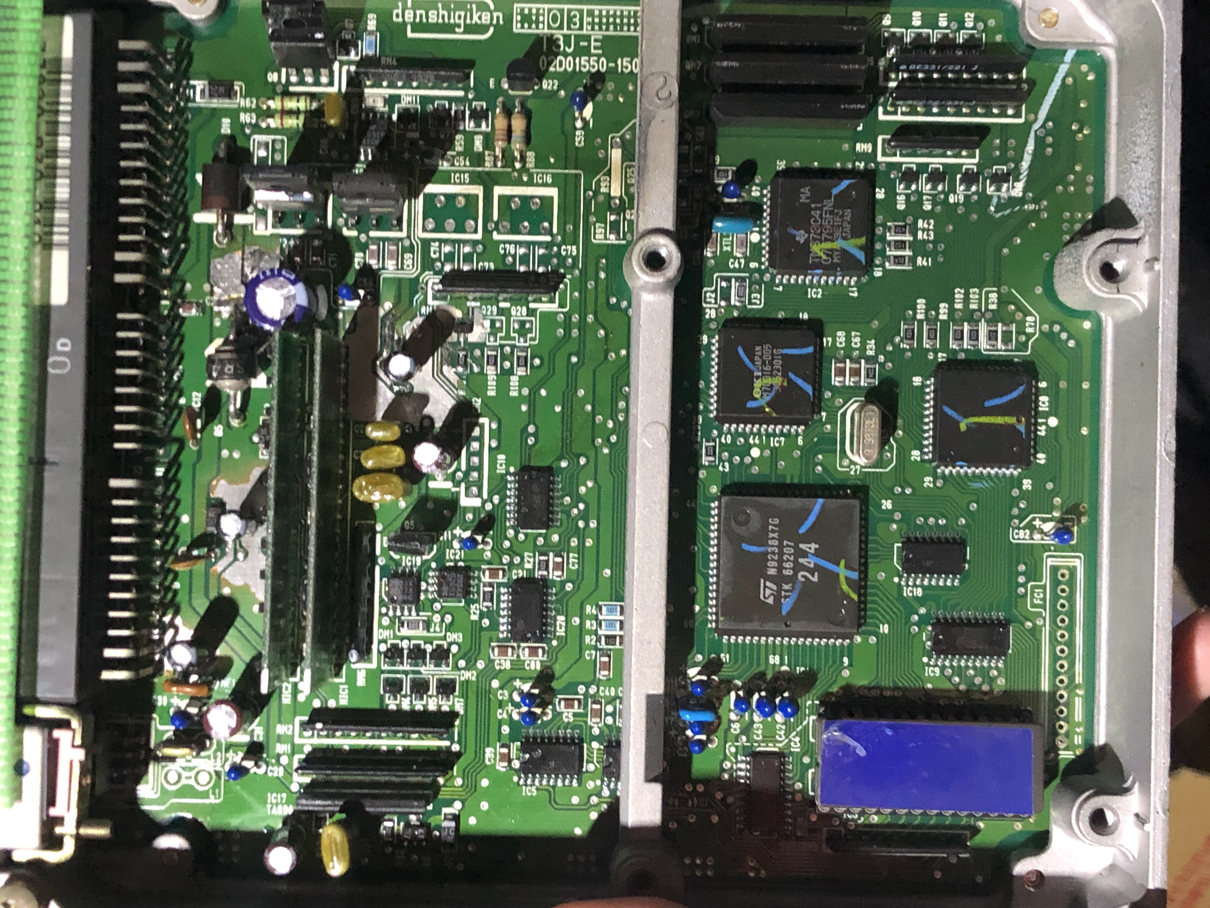
First, looking at the ECUs we had at hand, I checked what kind of ROM we were dealing with to find the correct datasheet. Most EPROMs were not exactly the same, but since they were all used for the same purpose, I assumed they all had the same pinout and thus just looked for one datasheet. The selected one was the Microchips 27C256 EPROM (29C256, AMD 27C256, STMicroelectronics M27C256B, etc would have worked the same). There was a nice reference of it and an ascii pinout on the PGMFI website which helped greatly. The 256 in the name means 256 kilobits, or 32 kilobytes, wich is 32768 addresses.
      +------()------+
  VPP |1           28| VCC
  A12 |2           27| A14
   A7 |3           26| A13
   A6 |4           25| A8
   A5 |5           24| A9
   A4 |6           23| A11
   A3 |7    27256  22| OE
   A2 |8           21| A10
   A1 |9           20| CE
   A0 |10          19| D7
   D0 |11          18| D6
   D1 |12          17| D5
   D2 |13          16| D4
  GND |14          15| D3
      +--------------+
You have 4 types of pins on such kind of ROM: the address bus, data bus, power supply related pins and “Enable” pins. This chip is a “Single voltage ROM”, which means you only need one voltage to read it (and an additionnal higher one to program it).
- Vpp is used to supply said high programming voltage (typically 25, 21 or 12.5v). We won’t need to bother about this just to read.
- Vcc is the normal power suply, of 5v. GND is the ground obviously.
- The 15 ‘A’ pins are the address bus. Each pin represents one bit of the address (A0 is bit 0, A1 is bit 1… etc until A14), so we can represent 15 bits address (0b111111111111111 is 0x7fff, the highest of the 32768 addresses). Driving those lines HIGH (bit set) or LOW (bit reset) will tell the ROM which address we are reading.
- The 8 ‘D’ pins are the data bus. Similarly to the address bus, each pins represent one bit of an 8 bits data byte. By reading those lines after setting the address bus’ pins, we can read one byte of data from the ROM.
- OE and CE are used to disable part of the chip to reduce power consumption, so we won’t really bother about it neither. The only main difference would be reading speed, but the chips we are dumping are already pretty fast so it’s fine~
In the end, we need to connect to all pins in this way:
- Drive 5v current to Vpp and Vcc.
- GND, OE and CE will be grounded.
- All ‘A’ pins will be “written” to individually by supplying HIGH or LOW voltage to them.
- All ‘D’ pins will be read individually and HIGH or LOW voltages will mean 1 or 0.
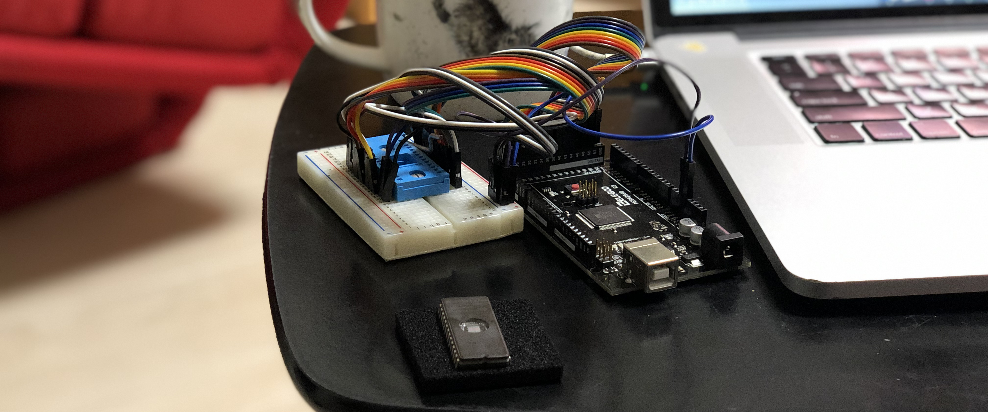
This means… we need a lot of pins and wires. By googling a bit more I found this article about this guy doing the exact same thing I wanted, but with a 14 bits address bus. He used an Arduino Mega, so I just took his code and modified it to match the 15bits of my chip and dump the code. Full explanation can be found on his article, and I wouldn’t want to copy paste it, so please check it out. My version of the code will be in the final repo too.
Now what?
Just for fun, I had previously started reversing my Integra’s ECU’s firmware (or a similar one I found on internet, since I didn’t really know how to dump mine like I had done with the Impreza). It runs an OKI 66207 CPU and the only available disassembler was a pretty old software named asm662 that was developped with the same ECUs in mind. It was a great source of information, but not very practical when you are used to IDA’s interface and tools, so I started writing a disassembler plugin for it. It is already on github as a work in progress, but it is already good enough to get an overview of the code (as written in the README, If you know how to handle special processor flags in IDA/idapython, I’m curious).
On the other hand, reversing those ECUs has been done before and the adresses are known to those who know where to look (some are on the internet, some are on old printed notebooks that Tuner-san had from when he worked on those years ago).
But before doing anything, what are the end goals? As I’m writing this line, I am just starting to look at the dumped firmware, with two goals in mind: the first one is to understand what my car’s tuning is, what differs from a stock ECU, etc. The second one comes from my Tuner-san’s request to make the rev limiter smoother, just for fun.
Interlude: Speed and rev Limiters
There are two well known limiters that people have mixed when reading my previous post about the Impreza, so I will describe them both here:
One is the speed limiter, which is related to the vehicle’s speed and is a requirement by law (at least here in Japan). The ECU monitors the speed of the car through the VSS’ signal and stops fuel injection when it goes over a certain limit (~180kph in Japan). It is then reactivated when the car goes below a certain speed (in practice with the Impreza, fuel cut happened at 188kph and reactivation happened at 184kph). This is not related to the engine, but just a safety measure to prevent cars from reaching their top speed from factory, and this is what I worked on bypassing in my last article. Fun fact: In Fast and Furious Tokyo Drift, this is the reason Han says that police cars won’t try to chase street racers if they are going over 180kph. However, this is not true anymore, as police cars are now legally the only cars without speed limiters from factory.
The other one is the rev limiter, which is a safety limiter used to prevent the cars from revving to the moon. Engines are designed to work in a specific rev range, going from around 900RPM at idling to redline (the red part of the tachometer). Going into redline is most of the time discouraged as it could destroy some internal parts of the engine, and power is usually lost there anyway. But since discouraging only wouldn’t make up for a driving mistake, the ECU also monitors the revs of the engine and cuts injection in a similar fashion when a certain value is reached. This is NOT something you should remove. When this fuel cut happens, the engine loses inertia and slows down, until the revs come back to a slower, safer value. Then injection is reactivated in the same way the speed limiter works.
When I talked to Tuner-san about the possibilities to probably modify and reflash custom firmwares, we knew that there was really no real reason to do so as he already has some high quality firmwares ready for those cars, but he did say that he would enjoy a smoother rev limiter: in those factory firmwares, fuel cut happens at 8300 RPM and reactivates at 8225 RPM, which is quite a big gap. This takes about a second for the car (in gear) to slow down and gives this jerky ON/OFF sensation when pushing the car to the limit. He mentionned it would be interesting to bring the cutoff/reactivation values closer to get a smoother limiter.
DISCLAIMER: Tuner-san builds race cars, where engine are pushed to the limit. If we manage to modify the firmware, we will only test it for a limited amount of time (to confirm we can) and revert back to a safer set of values. We don’t recommend you do that unless you know what you are doing, and the risks associated with it.
Then
The next part(s) of this article should be about reversing and, if possible, modifying/reflashing the chips (I’m already on it really, but I’m busy doing other things at the same time so I’m gonna release things bit by bit). Most scripts and code will be posted on this Github repo when the article is complete. Until then, feel free to ask your questions or tell me if anything sounds incorrect on Twitter.
And while you wait, on a completely non-computer-related topic, I invite you to check out what I do in my spare time in the Tokyo/Japan car scene on Kaeruzoku’s Youtube channel (english subs available).
Thanks for reading~
Update 2021/07/05: Part 2 now up!